
| Meat Thickness (mm) | t1 Lip Height (mm) | t2 Heating Time (Second) | t3 Iron Extraction Time (Second) | t4 Pressure Promotion Time (Second) | t5 Pressure Cooling Down Time (Minute) |
|---|---|---|---|---|---|
| <4,5 | 0,5 | 45 | <5 | 5 | 6 |
| 4,5 - 7 | 1 | 45 - 70 | <6 | 5 - 6 | 6 - 10 |
| 7 - 12 | 1,5 | 70 - 120 | <8 | 6 - 8 | 10 - 16 |
| 12 - 19 | 2 | 120 - 190 | <10 | 8 - 11 | 16 - 24 |
| 19 - 26 | 2,5 | 190 - 260 | <12 | 11 - 14 | 24 - 32 |
| 26 - 37 | 3 | 260 - 370 | <16 | 14 - 19 | 32 - 45 |
| 37 - 50 | 3,5 | 370 - 500 | <20 | 19 - 25 | 45 - 60 |
| 50 - 70 | 4 | 500 - 700 | <35 | 25 - 35 | 60 - 80 |
Polyethylene (PE) Pipe Stacking Rules
Polyethylene (PE) Pipe Staking Rules
- Proper and undamaged unloading of PE pipes on the site is one of the most important points of perfect assembly.
-
When transporting PE Pipes in the vehicle or forklift, attention should be given to sharp objects which are located on the attachment of crane machines.
- While unloading the PE pipes, attention should be paid to nails, stones, and pointed objects on the ground. To prevent pointed objects from damaging the pipe; the floor should be corrected and cleaned from the pointed objects’ nails, stones, etc.
- To prevent the pipes from touching the floor, 5 cm x 10 cm plank under 1-meter intervals should be placed.
- To prevent overlapping of pipes triangle wedges should be placed on the sides of the bottom row.
-
The stack height should not exceed 1.5 meters. The pipes in the lowest row should not be crushed and ovalized.
-
If the pipes will wait at the stacking area, they should be covered with tarpaulin to protect from sunlight (UV) and other natural phenomena.
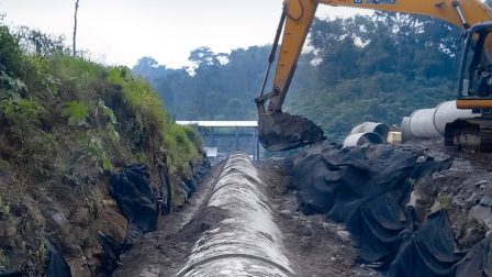
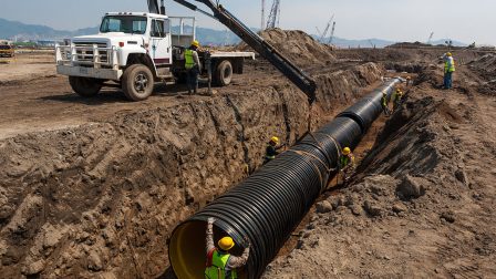
Polyethylene (PE) Pipe General Laying Rules
Correct assembly and proper bedding prolong pipe life. You can consult the ESEN Project Support Team in all matters related to pipe laying.
ESEN Project Support Team will be pleased to provide the required training at our factory or your construction site.
-
Damaged pipes should never be used.
-
Ground water should not be in the canal. If there is any, it should be discharged out of the canal with the means of a pump.
-
You can use ATV-A127 and EN 805 standards for Pipe Laying.
-
Canal / Trench base is opened according to the land level, should be free from sharp objects.
- To create the cushioning layer, it should be compacted and spread cushioning material (sand) 95%.
- To create the shirt Layer, soil material free from sharp objects should be poured 30 cm each and compressed by 95%. This process should be repeated every 30 cm.
- After the shirt layer compression process is finished, Soil filling is used to close the canal/trench.
Standard Tender Excavation Rules
On the lands with TRAFFIC LOAD, the filling area must be compressed according to the standards. CONCRETE shirting should be done under conditions that required floor depth cannot be provided.
| Load Type | Strength (kN) | Strength (lbs) | Depty of Embedment (m) |
|---|---|---|---|
| AASHTO H20 ( C ) | 72 | 16000 | 1 |
| BS 153 HA ( C ) | 90 | 20000 | 1,5 |
| ATV LKW 12 ( C ) | 40 | 9000 | 1 |
| ATV SLW 30 ( C ) | 50 | 11000 | 1 |
| ATV SLW 60 ( C ) | 100 | 22000 | 1,5 |
| Cooper E80 | Demiryolu | - | 3 |
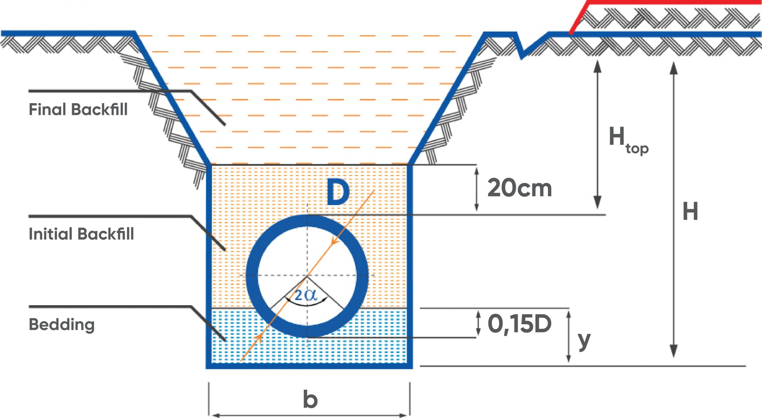
Polyethylene (PE) Pipe Trench Section
-
FINAL BACKFILL: Uncompacted soil filling. (Except for road crossings)
-
INITIAL BACKFILL: Compressed earth filling, free from hard objects
-
BEDDING: Compressed sand
- H: Trench Depth (cm)
-
Height top: The distance between the pipe top level and the ground (cm)
-
b: Trench Width (cm)
-
Y: Cushion Layer Height (cm)
- D: Pipe Outer Diameter (mm)
- 2a: Bedding Angle in Degrees
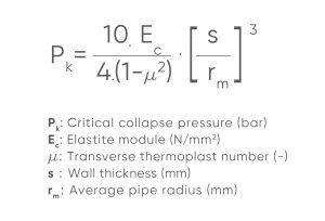
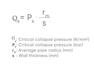
Collapse Pressure Calculations
Pipes laid under the ground have exposed some burdens outside the soil load. These can be loads that occur directly in the laying of pipes to the sea, such as sea discharge, or there may be extra loads created by groundwater when the pipe is laid under the ground.
Apart from these loads, pipes are intertwined by using the shirting method, lining concrete is made to fill the gap between pipes or in projects where there will be excessive stress, such as additional loads in vacuum-operated pipes for suction purposes, it is necessary to calculate stability (collapse).
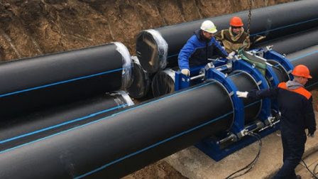
Polyethylene (PE) Pipes Welding Methods
BUTT WELDING METHOD
-
Butt Welding standard.ISO21307 / DVS2207
- Butt Welding Method is the most common welding method used in PE Pipes.
The surfaces of the pipes to be welded are transported to molten temperature and are left to cool under pressure.
-
PE Pipe should be made by certified people who have received training. (ESEN Project Support Team will be pleased to provide the necessary training at your factory or site.)
- Heater / Iron calibrated, a suitable machine should be used to the diameter of the pipe to be welded.
- It can be applied to wall thickness up to a minimum 3mm, maximum 150mm.
- It should not be more than a 10% difference between the wall shares of the pipes to be welded.
- Ambient temperature should not be under 5 ° C. If the ambient temperature is low, the area to be welded should be tented, and work- ing area should be shaped so as not to be affected by natural events such as cold, wind, precipitation, moisture, dust, etc.
- The end of the pipe should be closed in order to prevent welding heat from escaping due to air circulation.
- The welding ironing temperature should be between 200 ° C-230 ° C.
- After the ironing temperature reaches the desired value, wait 10 minutes and, it should be checked whether the desired value remains constant.
-
Pipe surfaces to be welded, Butt Welding Machine should be shaved with the shaving unit. Shaved surfaces again should not be polluted. Check if it is fixed.
- The pipe surface and welding iron should be cleaned with pure alcohol before every welding process.
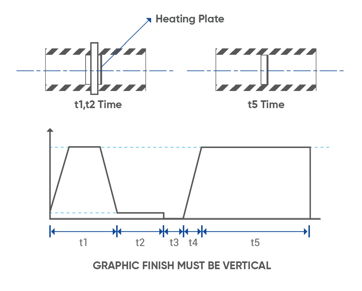
- t1= Pressure Heating Time with Pressure (WeldingPressure should be P = 0,15N / mm2,
Pipe lip height should reach L1
- t2= Heating Time
(Welding Pressure should be P <0.02N / mm2, Pipe Wall Thickness x10sec.)
- t3= Ironing Time
(This period should be kept as short as possible)
- t4= Pressure Rise Time
- t5= Cooling Time At Pressure
Electrofusion (EF) Welding Method
It is a method that provides the joining of PE pipes by welding by means of fasteners, the inner surfaces of which are covered with special resistance wires.
- The ends of the pipe to be welded are cut with a fine-toothed saw as straight/upright.
- The ends of the pipes should be scraped to the length that the sleeve will pass. In this way, surface oxidation is removed. After this process, the surfaces are stripped by scraper and should be cleaned with alcohol.
- Internal parts of the EF fittings to be welded should be cleaned with alcohol. It should be placed until the forehead of the pipe in the fittings.
- After the welding ends are placed on the EF coupling, the barcode on the coupling must be read to the machine.
-
The machine will start the welding process automatically according to the information on the barcode and finish the process at the end of the period.
How to Test Polyethylene (PE) Pipe Line?
Preparation Test
Before the main test, this test must be done to see if there are any leaks. One end of the line should be closed and must be filled with water.
- In order for the line to be filled completely, the air inside must be evacuated. After the line is completely filled with water, the line is closed.
- If the line is lower than PN6, it should be tested with PN x 1.5, if higher than PN6, it should be tested with PN + 5bar.
-
The line should be brought to the desired pressure in 10 minutes and the test pressure should be maintained by keeping the pump engaged for another 10 minutes.
-
The pump must be stopped and the pipeline should be taken on hold for 60 minutes.
-
After the waiting period has expired, in the pipeline no more than 30% pressure loss should be observed. If the pressure loss is more than 30%, a water leak or heat buildup is available. After the line is checked, The test should be repeated until there is no pressure loss.
-
If there is no pressure loss, it can proceed to the Main Test process.
Main Test
The pressurized pipeline continues to expand despite being exposed to pressure during the preliminary test. This expansion can be interrupted by Pressure Reduction.
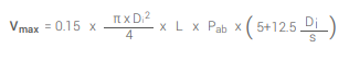
After the pressure is lowered, should waited 30 minutes for the line to complete the contraction time. During this process, if the pressure remains constant or if it is increasing, the sealing of the line is seen. If in doubt, the test can be extended up to 1.5 hours. Meanwhile, the pressure drop should be at most 0,25 bar. If it falls more, there is a leak in the line. The volume of water coming out during Pressure Reduction should be smaller than the maximum allowable water volume.
The maximum allowable water volume (Vmax) is calculated as follows.
- Vmax: Maximum permitted water volume (Liter)
- Di: Pipe inside diameter (m)
- L: Length of the tested line (m)
- Pab: Pressure drop (bar)
- S: Pipe wall thickness (mm)