
| Filling Material Group | Definition of Filling Materials |
|---|---|
| SC1 | Crushed stone containing less than 15% sand, maximum 25% amount of material |
| SC2 | Less than 12% fine grain containing clean coarse materials |
| SC3 | Clean coarse materials containing 12% or more fine grains Sandy or fine grains containing less than 70% fine grains |
| SC4 | Fine-grained materials containing more than 70% fine-grained piecess |
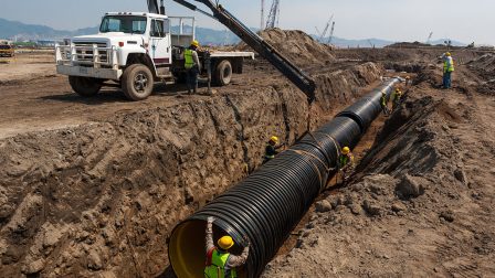
GRP Pipe Laying Procedure
The appropriate installation procedure for GRP Pipe varies depending on;
- rigidity of the pipe,
- the depth of the trench,
- the width of the trench,
-
the natural soil properties
-
the additional loads on the pipeline
-
the filling material
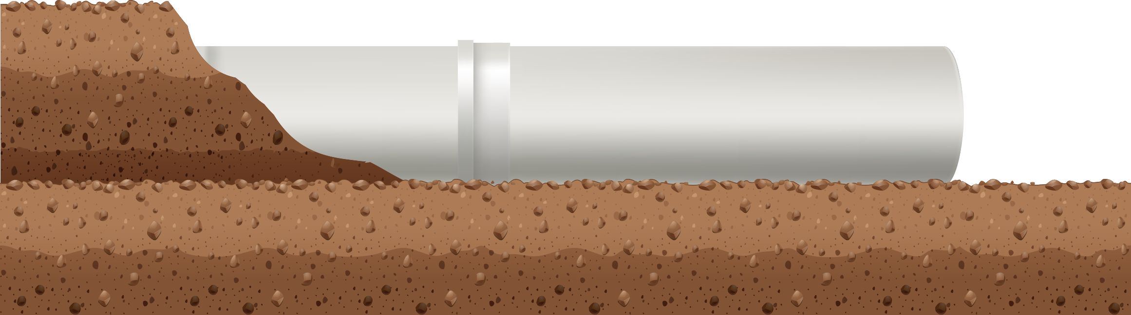
In order to support the pipe in a healthy way, the natural ground should be firmly wrapped around the pipe area filler.
The following pipe installation procedures are provided to assist in the proper laying of the pipe.
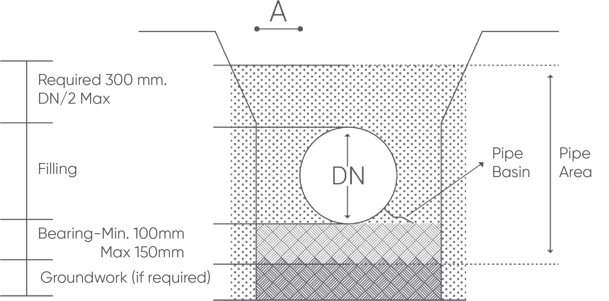
What is Standard Trench?
It shows the typical trench section dimensions.
The dimension “A” should always be wide enough to ensure that sufficient filling material can be placed and compacted in the pipe basin.
Dimension“A” should also be wide enough to allow the clamping equipment to operate in a manner that does not damage the pipe.
Typical ’’ A ’’ size, except for very small diameters, the minimum is 0.4 DN. For larger diameters, a smaller value for “A” may be appropriate, depending on the natural substrate, filler material, and compression technique.
For example, in the 1st, 2nd, and 3rd groups of natural soils, the trench can be kept narrower by using SC1 and SC2 fillers which do not require much compression.
NOTE: If soft, loose, unstable, or expanding natural ground is found on the bottom of the trench, it may be necessary to increase the thickness of the bearing pad to provide regular and unchanged support along the pipe.
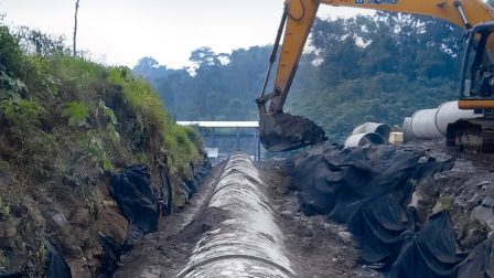
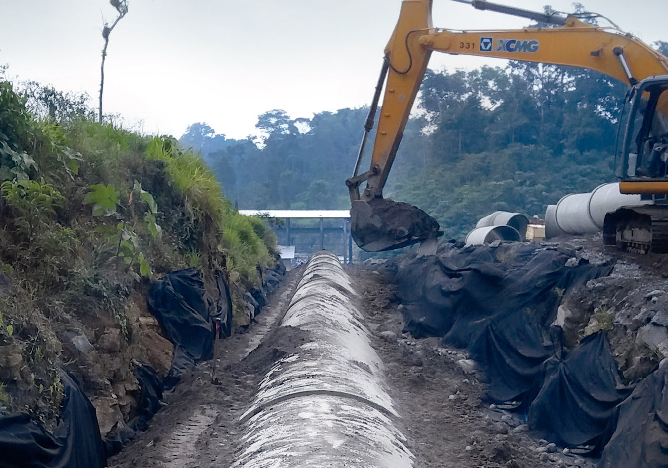
How to Fill a Pipe Trench?
The pipes may float due to heavy rainfall or may be exposed to thermal expansion, which may result from high temperature differences between day and night.
In order to avoid such nonconformities, it is recommended that each pipe, which has been completed, be filled to the surface level.
If pieces of the pipe are assembled but the filling process will pass; first, the joints in the middle of each pipe should be filled to the top to prevent movement.
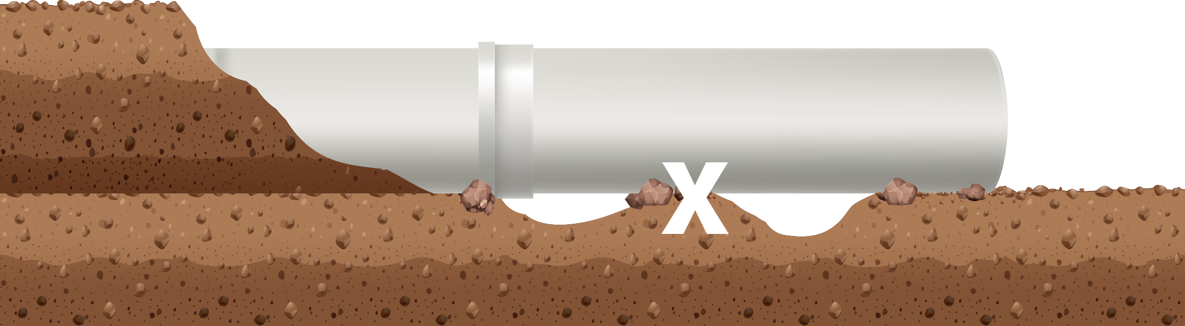
Correct selection and tightening of the pipe area filler are crucial for controlling vertical deflection and for pipe performance.
-
It should be ensured that the filling material does not contain trash and foreign materials which may damage the pipe and cause the lateral support to decrease.
-
The filling and compression of the material must be carried out before the remaining filling material is placed
-
The amount of energy consumed in the compression method should be checked as well as the thickness of the compacted fill layer. The appropriate filling process is generally carried out in layers between 100 mm and 300 mm thickness depending on the filling material and the compression method
- When gravel or crushed stone is used as the filling material, it is convenient for the filling layer thickness to be 300 mm, as these materials are relatively easy to compress.
-
Since thinner materials require more compression energy, the thickness of the filler layer should be limited. In order to support the pipe well, it should be ensuredthat each filling layer is well compacted.
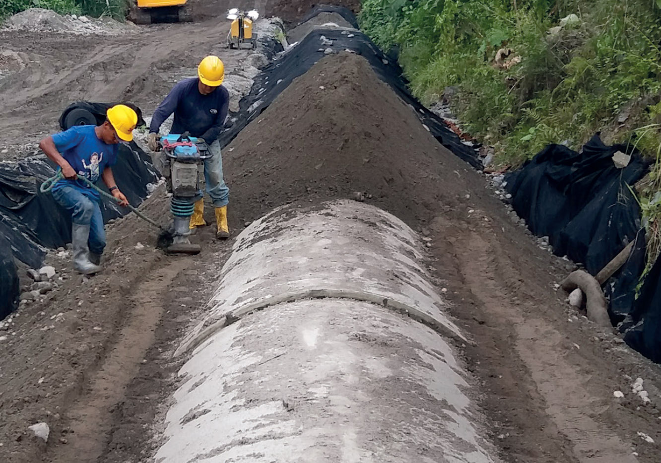
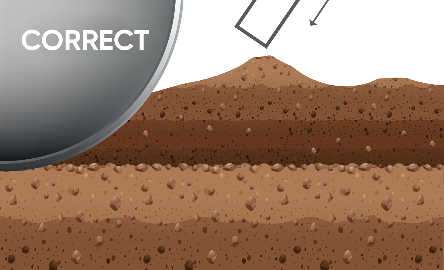
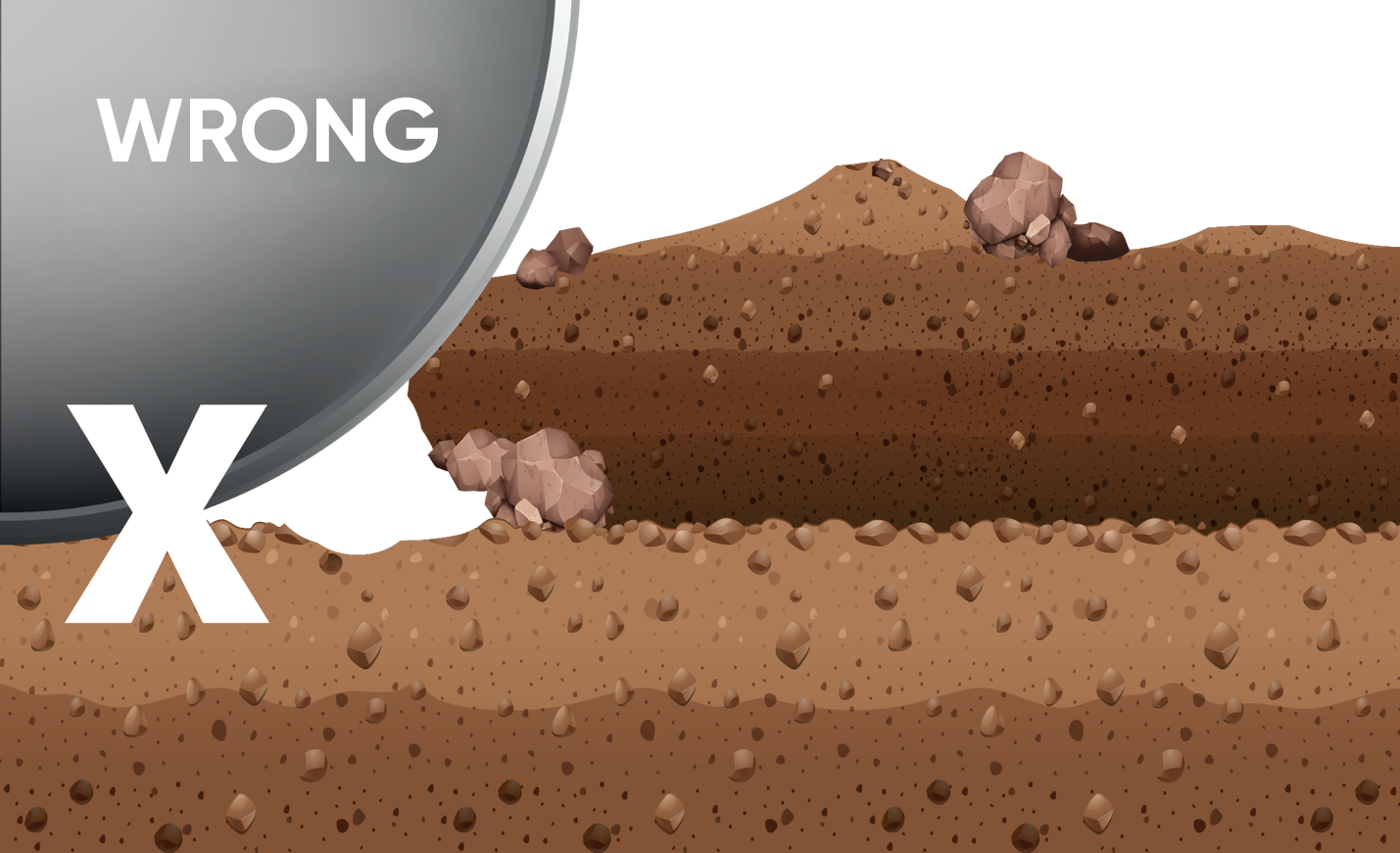
How To Make On-Pipe Compression?
When it reaches the top of the pipe, it should not exceed 1.5% of the pipe diameter.
This initial amount of ovalization will depend on the amount of energy required to achieve the desired relative degree of compression. High amounts of energy required for SC3 and SC4 fillers can cause this ovalization limit to be exceeded.
In this case, it can be considered the use of pipes or other filling materials of higher rigidity.
| Filler Type | Hand Operated Impact Plate Compactor | Hand Operated Vibratory Plate Compactor | Suggestions |
|---|---|---|---|
| SC1 | SC1 | Two-time transition provides a good compression. | |
| SC2 | SC2 | 2-4 transitions depending on desired density and height. | |
| SC3 | 100 - 200 mm | The number of transition and layer height depends on the desired density. Optimal or close moisture content. Check compression. | |
| SC4 | 10 - 150 mm | It may require high compression energy. Check that if the moisture content is ideal. Make sure that the compression is done correctly. |
With the Type 1 mounting version, the pipe area up to 300 mm in height must be tightened.
In areas that will be subject to traffic load, the trench filler is compacted to the natural ground to minimize road surface settlements.
It provides the thickness of the soil cover on the pipe required for the operation of various compaction equipment on the pipe.
Care should be taken not to apply high compression energy to the top of the pipe, which may cause deformity of the pipe circularity
| Permission initial vertical deflection values | Vertical Deflection (of Diameter %) |
|---|---|
| Large Diameter (DN 300) Begining | 3 |
| Small Diameter (DN 250) Begining | 2 |
Traffic Loads
| Load Type | Strength (kN) | Strength (lbs) | Depty of Embedment (m) |
|---|---|---|---|
| AASHTO H20 ( C ) | 72 | 16000 | 1 |
| BS 153 HA ( C ) | 90 | 20000 | 1,5 |
| ATV LKW 12 ( C ) | 40 | 9000 | 1 |
| ATV SLW 30 ( C ) | 50 | 11000 | 1 |
| ATV SLW 60 ( C ) | 100 | 22000 | 1,5 |
| Cooper E80 | Demiryolu | - | 3 |
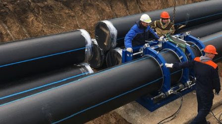
Double Sided Elastomer Sealed Coupling Mounting
The following steps (1-5) must be followed when fitting the Reka couplings.
-
Step 1: Foundation and Bearing
The bearing should be dug in such a way that at each point of the coupling, the headrests on the coupling prevent it from hanging and ensure continuous support of the pipe. After the jointing process is completed, the filling and bearing of the coupling area should be made properly.
-
Step 2: Cleaning the Coupling
The grooves of the double-sided couplings and the Epdm Reka seal to be placed in the couplings should be thoroughly cleaned until they are clear of dirt and oil.
-
Step 3: Installing the Seals
The elastomer seal is placed in the groove of the coupling such that the protrusions of the Epdm Reka seal are facing out of the groove. Do not apply lubricant into the groove or on the seal during gasket installation. However, the seal duct can be moistened with water for easy installation of the seals.
-
Step 4: Apply Lubricant to Elastomer Seal
Then apply a thin layer of lubricant to Epdm Reka Seal. The amount of lubricant that should be used in each coupling must be kept constant.
-
Step 5: Cleaning the Pipe Opening and Applying Lubricant
The pipe opening that will pass into the coupling must be cleaned from sand, dust, dirt, and oil. Check the sealing surface of the pipe opening for any damage. Apply a thin layer of lubricant to the area of the pipe up to the Pieces marked with a black strip. Make sure that the coupling and the pipe opening remain clean after the lubricant has been applied. A plastic sheet of approximately 1 m2 or a clean cloth to be placed under the jointing area has been found to be an effective way of ensuring that the pipe ends and seals remain clean.